|
|
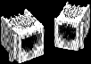
Corcom's Signal Sentry tm Filtered Modular Jack is a space saving and cost effective solution to RFI problems on signal lines. Its inductive and optional capacitive elements effectively strip common-mode noise from the incoming signal, and at t he same time limit the signal line's ability to radiate emissions like an antenna.
Conventional signal line RFI protection places discrete filtering components on the printed circuit board near the RJ connector. This consumes valuable space, sacrifices performance, and adds unnecessary complexity to the design and procurement processes. A better alternative, the unique Corcom design provides interference suppression at the optimal location by integrating the filtering into the RJ jack itself. Since the Signal Sentry tm matches the footprint of the unfiltered jack exactly, it is also a retrofittable solution to unforeseen RFI problems. (Shielded versions may require extra holes for the ground tabs.)
Signal Sentry tm products are useful for any electronic equipment that sends or receives data on unshielded twisted pair or other multi-conductor cabling systems. Modems, PBX'S, LAN, ISDN, and local I/O interfaces that use RJ connectors are all candidates.
Jack design and component selection compatible with equipment registered under FCC Part 68. UL Recognized. CSA Certified. Signal Sentry tm is covered by U.S. Patent No. 4,695,115 and U.S. Patent No. 4,772,224 and a variety of international patents.

A FAX/Modem board was being certified for FCC Class B emissions at an independent test laboratory. The board caused every computer it was tested in to exceed the radiated limits above 30 MHz, at multiples of each microprocessor's clock frequency, on t
he telephone line. The Test Lab
replaced the modem's unfiltered RJ11 jack with a Corcom RJ11-4L-B out of their sample kit, and the board/computer combinations passed with 4 dB margin worst case.

A RISC workstation designed to operate in a twisted-pair Local Area Network required two DIP package inductors and 12 chip capacitors to meet FCC radiated emissions limits. All 14 discrete components were eliminated by replacing the two RJ45 connectors
with two Corcom RJ45-8LCl-B shielded and filtered jacks, and the margin of emissions compliance actually improved.

A secure telephone set failed TEMPEST testing at a Government facility, due to intelligible emanations radiated from the coiled handset cord. The unit passed after the handset connector in the desk set was replaced by a Corcom RJH-4L-Bfiltered handset
jack.

A networked POS terminal was found to be out of compliance with FCC emissions limits, due
to radiation off the peripheral cable connected to its card-swipe reader. The problem was complicated by the fact that manufacturing was offshore, and a substantial inventory of custom printed circuit boards had already been procured. All problems went a
way, when the peripheral's RJ11 jack was replaced by an identical-sized Corcom RJ11-2L-S filtered jack.
WHAT TYPE OF CONNECTOR DO YOU NEED?
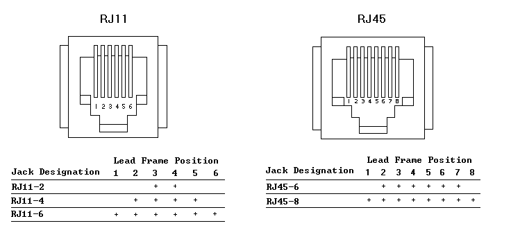
Handset jack four pin connectorRJHRJ11-4L1-B RJ11 six pin connectorRJ11RJ11-4L1-B RJ45 eight pin connectorRJ45RJ11-4L1-BHOW MANY TERMINALS WILL BE LOADED?
4 on RJH RJ11-4L1-B 2, 4 or 6 on RJ11RJ11-4L1-B 6 or 8 on RJ45RJ11-4L1-BWHAT LEVEL OF FILTERING PERFORMANCE DO YOU NEED?
No filter, connector onlyX modelsRJ11-4L1-B Inductor (block or bead)L modelsRJ11-4L1-B Inductor plus shieldLl or L2 modelsRJ11-4L1-B Inductor plus capacitors with shieldLCl or LC2 modelsRJ11-4L1-BDO YOU WANT A SHIELDED JACK?
(Optional on L models, N models, required on LC or LCT.) Panel and board ground (spring fingers on panel interface)1RJ11-4L1-B Board ground pins only2RJ11-4L1-B Board, Panel and Cable grounded (N Series)3RJ11-4L1-B Board and Cable Ground (N Series)4RJ11-4L1-BWHAT TYPE OF INDUCTORS DO YOU NEED?
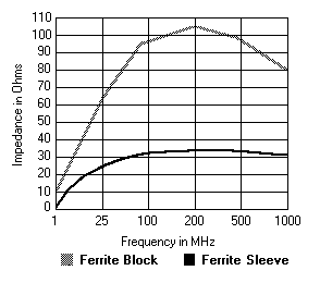
Sleeve -- Average performance*SRJ11-4L1-B Block -- Higher performanceBRJ11-4L1-B *Sleeve inductance is recommended in cases where crosstalk may be a problem.

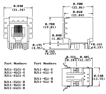
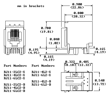
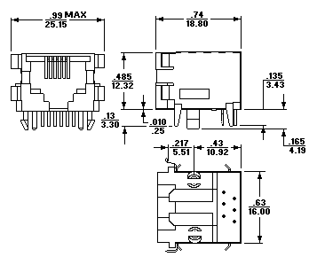
Inductive filtering in a direct retrofit to standard unfiltered RJ11, RJ45, or handset. Offered with standard ferrite sleeve inductors or higher performance ferrite block, the L Series is available with or without a shield.
Contacts

Material:Phosphor bronze
Plating:    50 microinches gold
Barrier underplating: 100 microinches nickel
Resistance:
   Initial:   20 milliohms maximum
   After durability testing
(500 mating cycles):   30 milliohms maximum
Ferrites

Type:  High resistivity, nickel zinc ceramic
Sleeves:     Single-aperature cylinders
Block:      Multi-aperature rectangular prism
Shield Material

Solder-plated copper alloy
Housing Material

Glass-filled polyester (UL94V-0)
Dielectric Withstanding Voltage

Line-to-line and line-to-ground:   1000 VAC for
     60 seconds
Printed Circuit Board Retention

Before soldering:  1 lb. minimum
After soldering: 20 lb. minimum
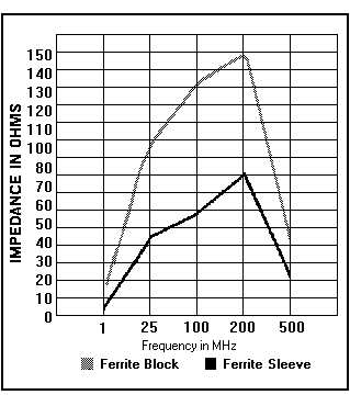
Capacitance components enhance the filtering performance in the LC models. Available with block or sleeve inductance, the additional chip capacitor provide additional filtering on each line. The series features shields with a board ground or spring finger panel interface.
Contacts

Material:Phosphor bronze
Plating:    50 microinches gold
Barrier underplating: 100 microinches nickel
Resistance:
   Initial:   20 milliohms maximum
   After durability testing
(500 mating cycles):   30 milliohms maximum
Capacitors

Type:Monolithic ceramic chip
Standard value: 820 pF
Standard tolerance: +/-20%
Ferrites

Type:  High resistivity, nickel zinc ceramic
Sleeves:     Single-aperature cylinders
Block:      Multi-aperature rectangular prism
Shield Material

Solder-plated copper alloy
Housing Material

Glass-filled polyester (UL94V-0)
Dielectric Withstanding Voltage

Line-to-line and line-to-ground:   1000 VAC for
     60 seconds
Printed Circuit Board Retention

Before soldering:  1 lb. minimum
After soldering: 20 lb. minimum
Typical Line-to-Line Insertion Loss in
50 ohm Circuit (passband)
| 30 | 60 | 80 | 100 | 200 | 500 | 1000 | |
| Ferrite Sleeves | |||||||
| Ferrite Block | |||||||
Typical Line-to-Ground Insertion Loss in
50 ohm Circuit (passband)
| 2 | 5 | 10 | 30 | 50 | 70 | 100 | |
| Ferrite Sleeves | |||||||
| Ferrite Block | |||||||
Capacitance components enhance the filtering performance but may alter the signal as it passes through the RJ Jack. A low capacitance model allows additional filter performance without significant effect on the signal itself. Corcom's new LCT models provide improved performance over L models without impact on the signal. These parts are particularly suited for ethernet applications.
These models are available in shielded models only, with either panel or board ground.
Contacts

Material:Phosphor bronze
Plating:    50 microinches gold
Barrier underplating: 100 microinches nickel
Resistance:
   Initial:   20 milliohms maximum
   After durability testing
(500 mating cycles):   30 milliohms maximum
Capacitors

Type:Monolithic ceramic chip
Standard value: 820 pF
Standard tolerance: +/-20%
Ferrites

Type:  High resistivity, nickel zinc ceramic
Sleeves:     Single-aperature cylinders
Block:      Multi-aperature rectangular prism
Shield Material

Solder-plated copper alloy
Housing Material

Glass-filled polyester (UL94V-0)
Dielectric Withstanding Voltage

Line-to-line and line-to-ground:   1000 VAC for
     60 seconds
Printed Circuit Board Retention

Before soldering:  1 lb. minimum
After soldering: 20 lb. minimum
Typical Line-to-Line Insertion Loss in
50 ohm Circuit (passband)
| 40 | 100 | 200 | 250 | 300 | 500 | 1000 | |
| Ferrite Sleeves | |||||||
| Ferrite Block | |||||||
Typical Line-to-Ground Insertion Loss in
50 ohm Circuit (passband)
| | | | | | 70 | 100 | |
| Ferrite Sleeves | |||||||
| Ferrite Block | |||||||
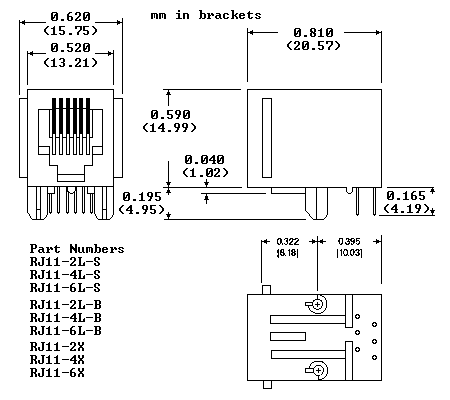
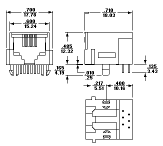
Low profile version of our Signal Sentry Series. Available with sleeve or block inductors and optional grounding shielding. Grounded shielding allows connection to grounded cables for additional RFI protection.
Contacts

Material:Phosphor bronze
Plating:    50 microinches gold
Barrier underplating: 100 microinches nickel
Resistance:
   Initial:   20 milliohms maximum
   After durability testing   30 milliohms maximum
PCB Terminals

Solderability  60/40
Ferrites

Type:  High resistivity, nickel zinc ceramic
Sleeves:     Single-aperature cylinders
Block:      Multi-aperature rectangular prism
Shield Material

Solder-plated phosphor bronze
Housing Material

Black glass-filled polyester    (Valox 457)
Dielectric Withstanding Voltage

Line-to-line and line-to-ground:   1000 VAC for
     60 seconds
Printed Circuit Board Retention

Before soldering:  1 lb. minimum
After soldering: 20 lb. minimum
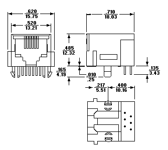
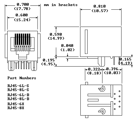
Corcom offers a standard, unfiltered jack both the RJ45 and RJ11 models to complement our filtered line.
Contacts

Material:Phosphor bronze
Plating:    50 microinches gold
Barrier underplating: 100 microinches nickel
Resistance:
   Initial:   20 milliohms maximum
   After durability testing
(500 mating cycles):   30 milliohms maximum
Housing Material

Glass-filled polyester (UL94V-0)
Dielectric Withstanding Voltage

Line-to-line and line-to-ground:   1000 VAC for
     60 seconds
Printed Circuit Board Retention

Before soldering:  1 lb. minimum
After soldering: 20 lb. minimum

A direct retrofit to handset connectors, the RJH models feature block inductance for optimal filtering of up to four lines.
RJ11
(Style 1 Shield)
RJ11
(Style 2 Shield)
RJ11
(No Shield)
RJ11 N Series
(No Shield)
RJ11 N Series
(Style 3 Shield)
RJ11 N Series
(Style 4 Shield)
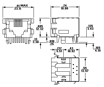
RJ45
(Style 1 Shield)
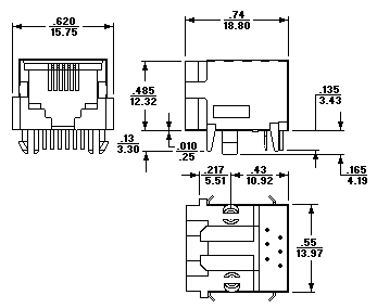
RJ45
(Style 2 Shield)
RJ45
(No Shield)
RJ45 N Series
(No Shield)
RJ45 N Series
(Style 3 Shield)
RJ45 N Series
(Style 4 Shield)
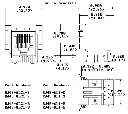
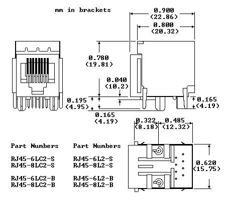
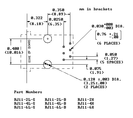
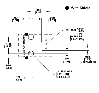
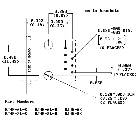
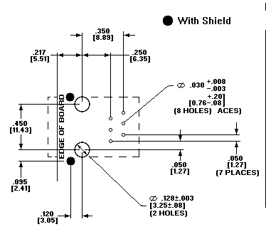
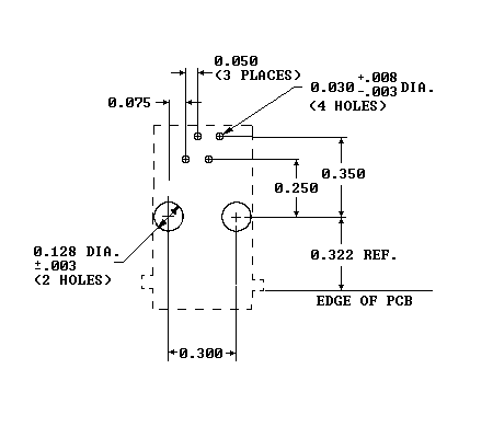
PC Board Layouts
RJ11
RJ11 N Series
RJ45
RJ45 N Series
RJH
(No Shield)
 E-mail